Raypak 337A Operations Instructions
Browse online or download Operations Instructions for Water heaters & boilers Raypak 337A. Raypak 337A Operating instructions User Manual
- Page / 55
- Table of contents
- TROUBLESHOOTING
- BOOKMARKS
- INSTALLATION AND OPERATING 1
- INSTRUCTIONS 1
- CONTENTS 3
- PART ONE 4
- MILLIVOLT SYSTEM 5
- ELECTRONIC IGNITION SYSTEM 6
- SECTION 2 - CAUTION 7
- SECTION 3 - MAINTENANCE AND 8
- CARE PROCEDURES 8
- IMPORTANT FREEZE INFORMATION 9
- PART TWO 10
- (Outdoor Stack) 12
- (Stackless Top) 12
- 206/266/336/406 Atmospheric 14
- SPECIFICATIONS AND DIMENSIONS 16
- ATMOSPHERIC UNITS 16
- Low NOx UNITS 17
- Optional Raypak D-2 18
- Power Vent 18
- Fig.# 8119.2 19
- Fig.# 8090.1 19
- (Invensys/Robertshaw) 20
- Fig.# 2012 21
- Fig.# 8095.1 22
- Fig.# 8097.1 22
- Fig.# 2011 22
- Fig.# 8093.1 22
- Fig.# 2002.1 22
- Fig.# 2003 23
- Fig.# 81.50.0 23
- Fig. #2004 23
- Fig. #9471 27
- Fig. # 9471.1 27
- Fig.# 9473 32
- Fig. #9472 32
- Fig.# 9480 33
- Fig.# 9482 35
- Fig.# 9485 35
- Fig.# 9440 38
- Fig.# 9439 38
- Fig.# 9438 38
- Fig.# 8152.3 38
- Fig. # 8045.1 Fig. # 8102.0 39
- Well Assembly 40
- Atmospheric Heaters 40
- Low NOx Heaters 40
- Fig.# 9412 41
- SECTION 5 - TROUBLESHOOTING 43
- Sensor Failure 46
- ATMOSPHERIC HEATERS 48
- LOW NOx HEATERS 49
- HONEYWELL MILLIVOLT PILOT 50
- IID LOW NOx PILOT 50
Summary of Contents
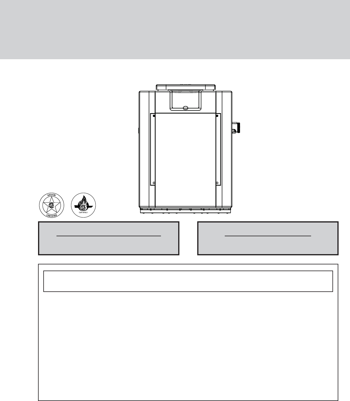
INSTALLATION AND OPERATING INSTRUCTIONSGAS-FIRED POOL AND SPA HEATERCATALOG NO. 6000.59E Effective: 02-01-06 Replaces: 12-16-05 P/N 241236WARNING: I
10PART TWOINSTALLATION AND SERVICE INSTRUCTIONSSECTION 1 - RECEIVING EQUIPMENTThe manufacturer recommends that this manual be reviewed thoroughly befo
11SECTION 3 - INSTALLATION INSTRUCTIONSCALIFORNIA PROPOSITION 65 WARNING: This product contains chemicals known to the State of Californiato cause can
12OUTDOOR HEATER INSTALLATIONThese heaters are design-certified for outdoor installation, when equipped with the approved tops designated foroutdoor u
13Heaters must not be installed under an overhang of less than three 3 ft from the top of the heater. Three sidesmust be open in the area under the o
14FLORIDA BUILDING CODE 2001WIND SPEED = 150 MPH, 3 SECOND GUSTEXPOSURE = CTOHB28”40”3” Min. Conc.Pad by others3” Min. Conc.Pad by othersMin. EdgeDist
15WARNING: Indoor heaters require a drafthood that must be connected to a vent pipe and properly vented tothe outside. Failure to follow this procedur
16SPECIFICATIONS AND DIMENSIONSHeaterModelBTUHInput(000)(A)CabinetWidth(B)FlueDia.(C)IndoorDrafthood(J)Min.GasConn.WaterConn.Shipping Weights (lbs)Sta
17Low NOx UNITSHeaterModelBTUHInput(000)(A)CabinetWidth(B)FlueDia.(C)IndoorDrafthood(J)Min. GasConn.WaterConn.Shipping Weights (lbs)StandardHeaterw/St
18B. All Air From Outdoors:When air is supplied directly from outside of build-ing, each opening shall have a minimum net freearea as noted:COMBUSTI
19The discharge opening must be a minimum of 2 ft ver-tically from the roof surface and at least 2 ft higher thanany part of the building within 10 ft
WATER CHEMISTRY(Corrosive water voids all warranties)For your health and the protection of your pool equipment, it is essential that yourwater be chem
20GAS PRESSURE REGULATORThe gas pressure regulator is preset at 4.0 in. WCthroughout for natural gas, and 10.5 in. WC. forpropane gas. The pressure a
21PLUMBING FOR WATER CONNECTIONSThe heater requires water flow and positive pressure to fire and operate properly. It must therefore be installeddown
22CAST IRON HEADERS (ASME MODELS)Heater must be located so that any water leaks will notdamage the structure of adjacent area. High tempera-ture 2&quo
23INTERNAL AUTOMATIC BYPASS VALVEIn addition to the Unitherm Governor, a built-in auto-matic bypass valve is provided in the in/out header.While the U
24HEAT EXCHANGER PRESSURE DROP TABLESPOLYMER HEADER (STANDARD MODELS)FLOWGPMPRESSURE DROP (FT OF HEAD)206/207 266/267 336/337 406/407201.5 2.8 4.1 4.1
25HEAT EXCHANGER REVERSAL PROCEDURE - STANDARD MODELS1. Remove right and left side access panels(Figure 1).2. Disconnect wires at high limit, AGS (aut
26ATMOSPHERICWiring locationsLOW NOxWiring locationsELECTRICAL WIRINGNOTE:If it is necessary to replace any of the originalwiring, use 105°C wire or i
27TRANSFORMER WIRING120 VAC WIRINGFor 120 VAC input power to the unit, connect the black wire to the “L1” or hot leg of the power supply. Connectthe w
28WIRING DIAGRAM - MILLIVOLT (MECHANICAL THERMOSTAT)
29WIRING DIAGRAM - DIGITAL MODELS - ATMOSPHERIC
4 PART ONEOWNER'S OPERATING INSTRUCTIONS4 SECTION 1START-UP PROCEDURES4 Before Start-Up5 Lighting Instructions & Shut-Off Procedures - Manual
30WIRING DIAGRAM - DIGITAL MODELS - LOW NOx
31SECTION 4 - SERVICING INSTRUCTIONSGENERAL LOCATION OF CONTROLSATMOSPHERICLOW NOxDigital Thermostat Circuit BoardDrain Plug(Located in rear header)Un
32CONTROL PANEL REMOVAL1. Remove (2) screws from front door. Set aside doorfor serviceability.CONTROL ADJUSTMENTS - MILLIVOLT MODELSThe water temperat
33THERMOSTAT CONTROL OPERATIONThe pool heater thermostat, located on the upper frontpanel of the heater, controls the pool/spa water tem-perature. Thi
34setResets board to factory default settings.Resets faults in the History File.Change from Fahrenheit to Celsius.SPA setpoint maximum adjustment.POOL
35If the PRS fault code is displayed, it indicates thatthere is insufficient water flow through the heater.Make sure the pool filter and pump strainer
36REMOTE CONTROL INSTALLATION AND OPERATIONCAUTION: Before installing remote controls to the digital thermostat model heaters read the following:The d
37REMOTE CONTROL WIRINGImportant Installation Notes for Remote or External Wiring Configuration• Remote wiring must be run in a separate conduit.• Rem
38WATER PRESSURE SWITCHThe water pressure switch, or heater actuator, ensuresthat the heater operates only when the filter pump is inoperation. It is
39PILOT REMOVAL AND CLEANING1. Disconnect pilot tubing and wires from gas valve.2. Remove pilot assembly from burner tray.3. Remove pilot from b
4PART ONE OWNER'S OPERATING INSTRUCTIONSFOR YOUR SAFETY - READ BEFORE OPERATINGWARNING: IF YOU DO NOT FOLLOW THESE INSTRUCTIONS EXACTLY, A FIRE O
40TUBE CLEANING PROCEDUREEstablish a regular inspection schedule, the frequencydepending on the local water conditions and the sever-ity of service.
41The Low NOx pool heaters are certified and testedunder the ANSI Z21.56/CSA 4.7 Standard for Gas-Fired Pool Heaters.The heater should be installed t
42LOW NOx HEATERS (CONTINUED)BURNER TRAY REMOVAL1. Shut off main electrical power switch to heater.2. Shut off gas upstream of heater.3. Remove front
43MECHANICALIMPORTANT NOTICE These instructions are intended for the use of qualified personnel who are specifically trained and experienced in theins
44ELECTRICAL - STANDING PILOT MILLIVOLTPOOL OR SPA HEATER ELECTRICAL CHECK WITH MILLIVOLT GAS VALVECAUTION: For qualified service personnel only.1. Fi
45STARTTURN GAS SUPPLY OFF.TURN THERMOSTAT(CONTROLLER) TO CALLFOR HEATPOWER TO PC BOARD?(24 V NOMINAL)YESSPARK ACROSSIGNITER/SENSOR GAP?YESTURN GAS S
46 Power OnIs the water temperature displayed?NOYESPush MODE switch to select "Pool" or "SPA"Push Temparrow to scroll todesired
47SECTION 6 - REPLACEMENT PARTSNOTE: To supply you with the correct part, it is impor-tant that you supply the heater model number, serialnumber and
4810-M14-M9-M9-M5-C4-C11-S4-S5-S3-B4-B5-B1-B6-S7-S4-S2-R1-R1-J16-M3-R2-V4-V1-V3-V1-S13-S2-S12-S4-HP5-HP7-HP6-HP6-HP3-HP12-HM17-HM14-M8-S2-J2-B1-G4-M2-
498-S3-S11-S4-S6-S7-S4-S5-S1-R1-J2-S3-R9-M1-V2-V3-V1-S2-S12-S13-S9-M17-HM12-HM4-HP3-HP6-HP5-HP7-HP6-HP2-J1-G4-B3-B6-B5-B1-B10-S3-J2-B2-M10-M4-C6-C6-M8
5CAUTION:Propane gas is heavier than air and will settle on the ground. Since propane can accumulate inconfined areas, extra care should be exercise
5016-HM15-HM12-HM9-HM10-HM2-C3-M11-HM8-HM(OPTIONAL)3-M 5-C19-HP11-HP16-HP10-HP13-HP14-HP17-HP18-HP8-HP15-HP12-HP2-HP1-M(OPTIONAL)1-CPOLYMER IN/OUT HEA
51CALLOUT DESCRIPTION 206A 266A 336A 406AB BURNER TRAY 1-B Burner Tray w/Burners (sea level)* 010391F 010392F 010393F 010394FBurner Tray w/o Burners (
52CALLOUT DESCRIPTION 206A 266A 336A 406AHM HEAT EXCHANGER - METAL1-HM Heat Exchange Assy.Copper ASME CI 010051F 006727F 010053F 010054FHeat Exchange
53CALLOUT DESCRIPTION 206A 266A 336A 406AS SHEETMETAL1-S Jacket Top (Louvered) 010047F 010048F 010049F 010050F2-S Flue Collector (Units with Polymer H
54CALLOUT DESCRIPTION 207A 267A 337A 407ABB BURNER TRAY 1-B Burner Tray w/Burners (0-5000) 010343F 010344F 010345F 010346FBurner Tray w/o Burner (0-50
55CALLOUT DESCRIPTION 207A 267A 337A 407AJ CONTROL BOX1-J Transformer 120/240/24V 006736F 006736F 006736F 006736F2-J Rocker Switch 009493F 009493F 00
6CAUTION: Propane gas is heavier than air and will settle on the ground. Since propane can accumulate inconfined areas, extra care should be exercis
7AFTER START-UPFeel the inlet and outlet pipes. Outlet pipe should beonly slightly warmer than the inlet. It should not be hot.VISUAL INSPECTION - A
8SECTION 3 - MAINTENANCE AND CARE PROCEDURESTo be followed one month after start-up and then semi-annually.1. Inspect top of heater and drafthood for
9COLD WEATHER OPERATIONIMPORTANT FREEZE INFORMATIONMODERATE CLIMATE: Heater operation can contin-ue during short-term cold spells. When temperaturesa
More documents for Water heaters & boilers Raypak 337A


Related products and manuals for Water heaters & boilers Raypak 337A
 (131 pages)
 (90 pages)
© 2020, manymanuals.com. All rights reserved. | 0.180 s |
 Manymanuals.com
 Manymanuals.de
 Manymanuals.fr
 Manymanuals.it
 Manymanuals.pl
 Manymanuals.cz
 Manymanuals.es
 Manymanuals-pt.com
Comments to this Manuals